
Newsletter Sign Up
Subscribe to get the latest news and updates. No spam , we promise.


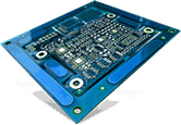
The functionality and shelf life of most electrical systems heavily rely on the integrity and functioning of rigid-flex printed circuit boards (PCBs). Rigid PCBs combine both rigid and flexible board technologies, making them ideal for several industrial applications. An added flexibility allows OEMs to maneuver these boards with ease during the installation process. Before capitalizing on rigid-flex PCBs, it is important to understand their design guidelines. This is because a design flaw considerably affects the overall performance and productivity of the board. Also, when detected at a later stage, it adds to the cost and time of manufacturing the boards. This post focuses on the manufacturing practices and standards that help in producing rigid-flex PCBs with supreme quality and functionality. So, stay tuned.
When manufacturing rigid-flex PCBs, it is important to consider some standard guidelines. These guidelines can act as a checklist for creating rigid-flex circuit boards without any manufacturing defects.
As the name implies, these PCBs are made of alternate layers of rigid and flexible materials. Therefore, it is important to decide on manufacturing processes and materials depending upon the number of layers required for the intended use. Based on the application requirement, you can decide upon the grade and type of copper, the total number of layers, and the appropriate manufacturing method. You also need to consider resistance to shocks, vibrations, frequent moves, and so on if the application so demands.
It is a good practice to keep copper traces at right angles to the rigid-flex boards because it works well when placed that way. Thus, strictly avoid bending the circuit board corners as it strains copper traces. However, in some situations it’s unavoidable. In those cases, one could use conical radius bends.
Copper on the circuit board detaches from a polyimide substrate due to the repeated stress caused by bending and lower adhesion. Therefore, it is important to provide copper traces with enough pad support. Many times, it could be ineffective so in that case, one can increase the reliability of pads using a coverlay mask.
Consider utilizing hatched polygons to retain the high-level flexibility of the circuit board. Using a normal hatched polygon retains copper stresses in different angle directions - 0°, 90°, and 45°. Usage of solid copper pours results in buckling of copper and reduced flexibility under tight radius bends.
To avoid fatigue caused by repeated bending, it is recommended to keep at least ½ mm clearance between the copper annulus and adjacent vias. Try to place the vias in stationary areas, where they are not subjected to repetitive bends and stresses. Additionally, one can make use of the layer stack manager to define each rigid sections, which eventually flex but with a rigid dielectric material adhered to them.
If you are someone who is trying to use non-standard base dielectric materials and adhesiveless laminates, then contact the raw material supplier during the early design phase. Nowadays, they are available in standard sizes; however, it may take extra time to deliver them to your doorstep. It is recommended to avoid these materials until the design conditions demand using them.
The above-mentioned guidelines would help manufacturers produce reliable, performance-driven rigid-flex PCBs. Are you looking for rigid-flex PCBs for your next electronics application? If that sounds yes, then you must employ an industry leader who will assist you throughout the process. With years of market presence, Creative Hi-Tech specializes in manufacturing and designing rigid-flex PCBs.
Related Blog Posts: