
Newsletter Sign Up
Subscribe to get the latest news and updates. No spam , we promise.

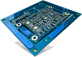
Ball grid array (BGA) has advanced from pin grid array (PGA) PCB packaging technology. This technology includes the positioning of small balls in a particular manner on electronic boards using surface mount technology (SMT). This technology is rapidly replacing the dual-in-line and flat packaging techniques. Although it has become a standard element in modern PCB packaging, it is not widely accepted like other technologies. In order to fulfill the acceptance criteria, the evaluation of ball grid packaging is essential. This post discusses the acceptance criteria of ball grid array challenges and a few techniques to inspect the same.
The ball grid PCB assembling or packaging technology is one of the complex packaging technologies, the conventional inspection methods do not suffice. Therefore, PCB manufacturers are facing a higher rejection rate. Although there is a lack of defined industrial documentation to increase the success rate of the BGA devices the following acceptance criteria are helpful.
Further, these types of PCBs are accepted if minimum defects are found. These PCBs are often inspected for the following defects.
The solder reflow profile must be performed with appropriate thermal management. Since the BGAs may involve high-density regions where a large number of metallic balls are placed, such locations require critical thermal management. The solder reflow traces are inspected for acceptance.
The internal voids in the solder joints should not exceed 20% size of the ball diameter.
Misalignments
Missing metallic balls
Non-wetted pads
Partial reflow
Under the BGA evaluation, three types of inspection are covered, namely, optical, mechanical, and microscopic inspection.
The optical inspection involves visual testing of circuit boards. Since visual inspection with naked human eyes does not suffice for this type of PCB evaluation, therefore the optical inspection under an endoscope is performed.
The mechanical inspection of these PCBs is a destructive method. Since they are subjected to external forces, vibrations, shocks, and electrical fluctuations. Therefore, these ball grid PCBs are tested by shock tests, scrap tests, etc.
The microscopic inspection is for voids or defects lower than 10 microns. One or more of the following techniques of microscopic evaluation are used for the inspection.
X-ray laminography is a technique commonly utilized for flat surfaces. Since the gap between metallic balls is negligible in these PCBs, this technology is used to test under layer uniformity of the board surface. CCD-camera radiographic images are captured from various angles of the board to conclude the surface condition of the board.
The standard trans-missive x-ray test is performed on the PCBs to test potential micro defects. Generally, defects like micro-voids, misalignments, etc., are inspected using this technique. Also, the ball circularity, concentricity, pitch, etc., can be tested by using emissive x-ray inspection.
Acoustic micro-imaging is the non-destructive inspection method used for microscopic inspection of ball grid PCBs. It is used to check if there are any cracks, voids, or delamination on the surface.
In order to ensure the proper functioning of the ball grid array, it is important to source them from experienced PCB manufacturing services like Creative Hi-Tech. They have 20 years of experience in PCB manufacturing and can assist you with BGA assembly and rework and repair processes.
Related Blog Posts: